
Most buyers assume die-cutting is a straightforward process—send us a drawing, we punch your shape, done. But after years of handling trial production and failed orders, I can tell you this: not every material behaves the way you expect under a blade. Some materials collapse mid-cut, others stretch out of tolerance, and a few look perfect until you try to peel them off the liner. The question isn't just "can you die-cut this material?" It's "will this material hold the shape I actually need?"
Not all tape materials can be die-cut into any shape you want. The material's elasticity, thickness, adhesive strength, and structural stability determine whether your design is manufacturable—and buyers who skip trial sampling often discover this too late, after committing to MOQ and delivery deadlines.
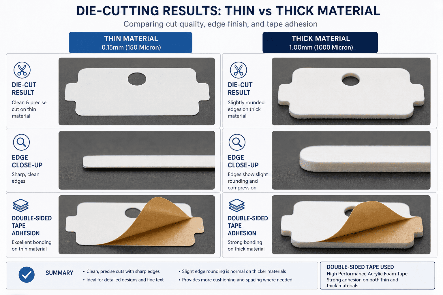
If you've ever received a sample that looked nothing like your CAD drawing, or been told "this shape is not feasible" after submitting an order, you already know what I'm talking about. Let me walk you through what actually happens on the production floor when we evaluate whether your material can be die-cut—and how you can avoid wasting time and money on orders that were never going to work.
Why Do Some Materials Fail Die-Cutting Even When the Drawing Looks Simple?
Most buyers think die-cutting is just pressing a blade through tape. If the blade is sharp enough and the machine is strong enough, any shape should be possible, right? Not quite. I've seen orders where the drawing was a basic circle, but the material stretched into an oval during cutting. I've also seen intricate designs work perfectly on PET film but completely fail on foam tape using the exact same tooling.
The reason some materials fail die-cutting has nothing to do with the complexity of your design—it's because the material's physical response to blade pressure makes it impossible to hold the shape you specified, especially when tolerances are tight or the design includes sharp corners and narrow bridges.
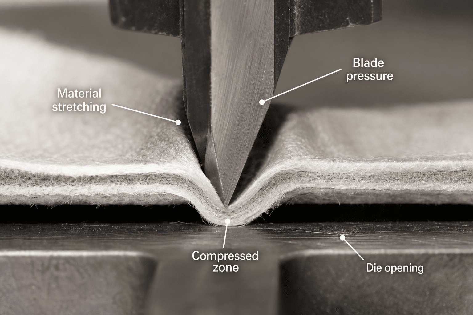
Here's what actually happens during die-cutting: the blade applies downward force to cut through the material, but the material doesn't just split cleanly like paper[^1]. Depending on its elasticity, thickness, and internal structure, it may compress, stretch, tear unevenly, or spring back after cutting. Foam materials compress under blade pressure and sometimes don't return to their original thickness[^2]. High-stretch films elongate during cutting and shrink afterward, throwing off your dimensional tolerances[^3]. Brittle films crack instead of cutting cleanly, leaving rough edges that won't pass quality inspection.
We run trial production specifically because material behavior under real cutting conditions cannot be predicted from a spec sheet alone. A material might have perfect adhesive strength and the right thickness on paper, but if it stretches 2mm during die-cutting, your 10mm diameter circle becomes an oval, and your entire batch is scrap. This is why experienced buyers always request sampling before committing to full production—they know that "can be die-cut" and "can hold your exact shape within tolerance" are two very different questions.
The key variables that determine die-cutting feasibility are material elasticity, structural stability under compression, adhesive behavior during cutting, and post-cut shape retention. Buyers who understand these variables upfront can filter out problematic materials early and avoid the frustration of failed first orders. Buyers who assume everything is cuttable end up learning this lesson the expensive way.
| Material Property | Impact on Die-Cutting | What Buyers Should Ask |
|---|---|---|
| High elasticity (stretch) | Shape distortion during cutting, tolerance drift after release | Will the material return to original size after blade pressure is removed? |
| Low structural rigidity | Collapse or compression under blade force, inconsistent edge quality | Can the material maintain thickness and flatness during cutting? |
| Strong adhesive coating | Blade gumming, uneven cuts, difficulty separating waste material | Does the adhesive layer interfere with blade sharpness during repeated cuts? |
| Brittle or stiff structure | Cracking, chipping, rough edges instead of clean cuts | Will the material fracture instead of cutting cleanly under blade pressure? |
If your material has any of these characteristics, you need to discuss feasibility with the factory before finalizing your design. Some materials require custom tooling, modified blade angles, or adjusted cutting speed to work properly. Others simply cannot hold certain shapes no matter what adjustments we make. The earlier you identify these limitations, the faster you can adjust your design or switch materials—and avoid wasting weeks on trial production that was never going to succeed.
Does Material Thickness Determine Whether Die-Cutting Will Work?
Buyers often assume that thicker materials are harder to die-cut, and thin materials are always easier. This makes intuitive sense—less material means less resistance, right? But in practice, I've seen 3mm foam tape die-cut perfectly into intricate shapes, while 0.1mm PET film failed because it wrinkled during cutting. Thickness matters, but not in the way most people think.
Material thickness affects die-cutting feasibility, but the real variable is how thickness interacts with the material's structural stability and elasticity—thin materials can fail if they lack rigidity, and thick materials can succeed if they compress evenly under blade pressure.
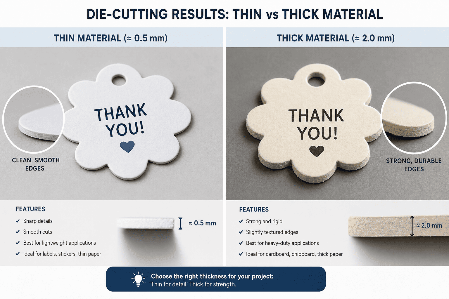
Here's the reality: when we die-cut thin materials like 0.05mm PET film or tissue tape, the material has almost no structural rigidity. During cutting, the blade pushes the material downward before it cuts, causing wrinkling, folding, or uneven edge quality. If the adhesive layer is too strong, the material sticks to the blade during cutting and tears instead of separating cleanly. Thin materials also have a tendency to curl or distort after cutting, especially if the design includes narrow strips or small holes.
On the other hand, thick materials like 3mm foam or 5mm butyl tape have their own challenges. The blade needs to penetrate deeper, which increases the risk of blade dulling and inconsistent cut depth. If the foam has high elasticity, it compresses during cutting and springs back afterward, throwing off dimensional accuracy. If the material is too dense, the blade may not cut all the way through on the first pass, requiring multiple cutting cycles that slow down production and increase cost.
The sweet spot for die-cutting is usually materials between 0.5mm and 3mm thickness[^4] that have moderate elasticity and good structural stability. These materials cut cleanly, hold their shape after cutting, and separate from the waste material without tearing or leaving adhesive residue on the blade. But even within this range, material behavior varies widely depending on composition, adhesive type, and liner strength.
When you're evaluating whether your material can be die-cut, don't just look at thickness alone. Ask yourself: does the material have enough structural rigidity to resist wrinkling during cutting? Will it compress or stretch under blade pressure? Can it hold its shape after the blade is removed? If you can't answer these questions confidently, request a trial sample before committing to production.
| Thickness Range | Common Die-Cutting Challenges | Best Practice for Buyers |
|---|---|---|
| 0.01mm – 0.1mm (ultra-thin films) | Wrinkling, tearing, adhesive transfer to blade | Verify that the material has sufficient liner support and low adhesive tack |
| 0.1mm – 0.5mm (standard tapes) | Edge curling, dimensional drift after cutting | Request tolerance testing before finalizing design |
| 0.5mm – 3mm (foam and thick tapes) | Compression, spring-back, inconsistent cut depth | Confirm that the factory has blade depth control for thick materials |
| 3mm+ (specialty gaskets, butyl) | Blade dulling, slow cutting speed, high waste rate | Expect longer lead times and higher tooling costs |
If your material falls outside the standard thickness range, don't assume it's impossible to die-cut—but do expect that the factory will need to adjust tooling, cutting speed, and quality control procedures to make it work. Some materials require rotary die-cutting instead of flatbed cutting[^5], which affects cost and minimum order quantity. The key is to communicate your material specs clearly and request trial production early, so both sides understand what's realistic before committing to large-scale orders.
Can Foam Materials Be Die Cut Into Complex Shapes?
Foam tape is one of the most commonly die-cut materials in industrial applications, but it's also one of the most misunderstood. Buyers love foam for its cushioning, sealing, and vibration-damping properties—but they often underestimate how difficult it is to die-cut foam into precise shapes. I've seen orders where customers requested intricate foam gaskets with tight tolerances, only to discover during trial production that the foam couldn't hold the shape at all.
Foam materials can be die-cut, but their high compressibility and elastic recovery make them unsuitable for designs that require sharp corners, narrow bridges, or tight dimensional tolerances—buyers need to adjust their design expectations based on foam density and cell structure.
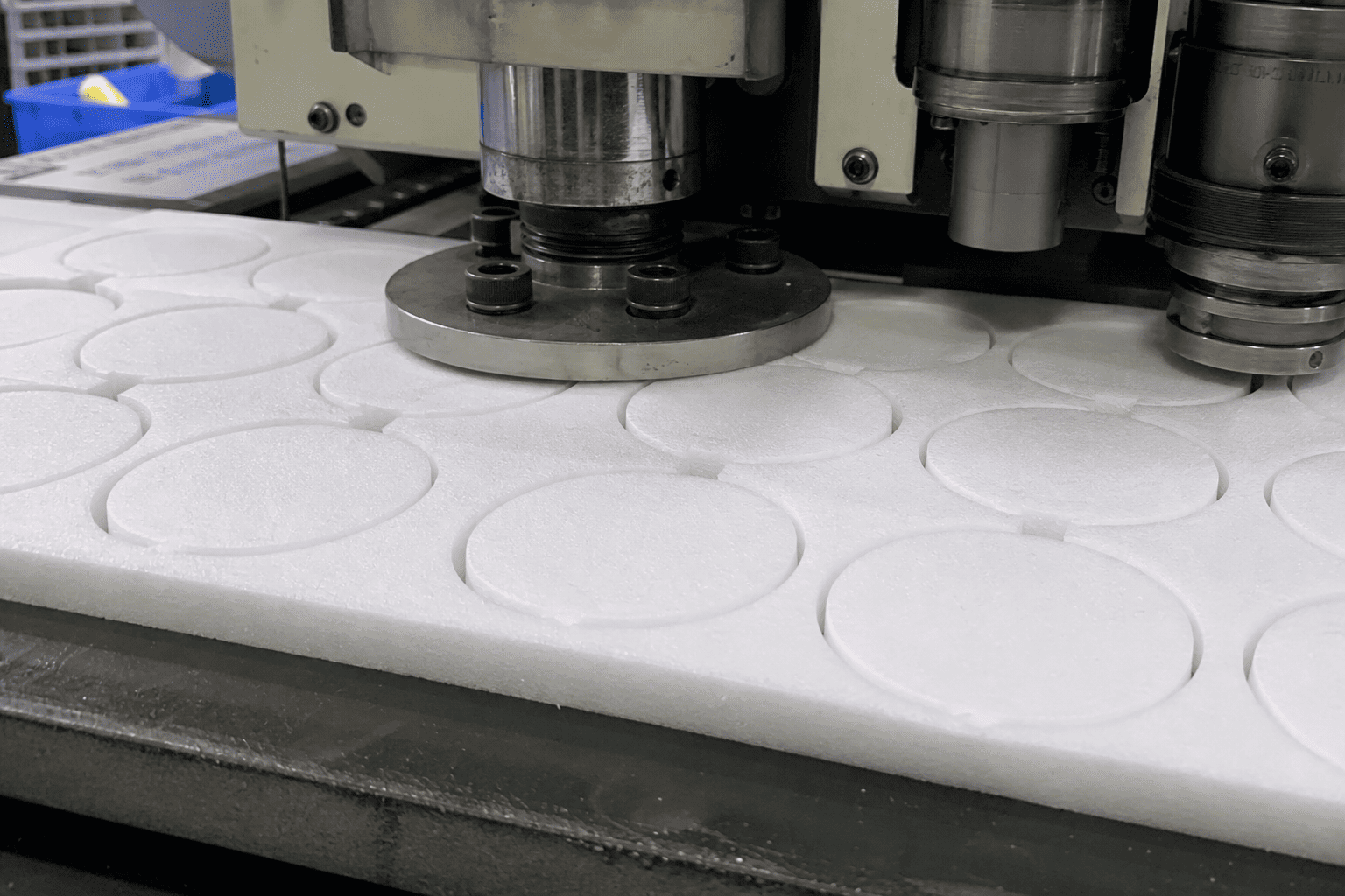
Here's what happens when we die-cut foam: the blade presses into the foam, compressing the cell structure before it actually cuts through[^6]. Because foam is designed to absorb impact, it resists the blade rather than splitting cleanly. This compression causes two major problems. First, the foam may not return to its original thickness after cutting, leading to dimensional inaccuracy. Second, the compressed edges may have a "crushed" appearance instead of a clean, sharp edge, which can affect sealing performance in precision applications.
High-density foam (closed-cell foam, EVA foam, PE foam) generally die-cuts better than low-density open-cell foam[^7] because it has more structural stability and less elastic rebound. But even high-density foam has limits. If your design includes sharp 90-degree corners, the foam will compress at the corner during cutting and may tear or round off instead of holding the angle. If your design includes narrow bridges (gaps between cut sections), the foam may stretch or collapse during cutting, making it impossible to maintain the specified gap width.
Low-density foam (open-cell sponge, polyurethane foam) is even more challenging. These materials compress easily, spring back unpredictably, and often tear unevenly during cutting. If the foam has a strong adhesive backing, the adhesive layer can pull the foam out of shape as the waste material is removed, distorting the final part. This is why we always recommend trial sampling for foam materials—what looks simple on a CAD drawing often reveals serious manufacturability issues once you start cutting real material.
When you're designing die-cut foam parts, here are the practical guidelines I give to customers: avoid sharp internal corners (use radiused corners instead), avoid gaps narrower than 3mm between cut sections[^8], avoid tolerances tighter than ±0.5mm unless you're willing to accept higher waste rates[^9], and avoid designs that rely on perfectly straight edges (foam edges will always have some degree of compression texture). If your application requires precision sealing or exact dimensional fit, foam may not be the right material—consider switching to PET film with foam backing, or using a denser material like rubber or silicone gasket.
| Foam Type | Die-Cutting Suitability | Design Limitations |
|---|---|---|
| Closed-cell EVA foam | Good – moderate compression, clean edges | Avoid tolerances tighter than ±0.5mm |
| Closed-cell PE foam | Good – low adhesive transfer, stable thickness | Minimum gap width: 3mm between sections |
| Open-cell polyurethane foam | Poor – high compression, uneven edges | Not suitable for precision shapes or tight tolerances |
| Acrylic foam tape (VHB type) | Moderate – high adhesive strength causes stretching during cutting | Requires slow cutting speed and careful waste removal |
If you absolutely need foam material for your application, be prepared to adjust your design based on trial production results. The factory may need to use custom blade angles, slower cutting speeds, or specialized waste removal techniques to make it work. In some cases, we can achieve better results by laminating foam to a rigid backing material before die-cutting, which prevents compression and improves dimensional accuracy. But all of these solutions add cost and lead time—so the earlier you discuss foam die-cutting feasibility with the factory, the better your chances of getting a manufacturable design on the first try.
Why Do Some Materials Look Perfect After Cutting But Fail During Application?
This is one of the most frustrating scenarios for buyers: you receive a sample, the die-cut shape looks perfect, the edges are clean, the dimensions match your drawing—and then you try to apply the part to your product, and it falls apart. Maybe the adhesive doesn't stick. Maybe the material tears when you try to peel it off the liner. Maybe the shape distorts the moment you press it onto a curved surface. I've seen this happen countless times, and it always comes back to the same issue: the material passed visual inspection, but it wasn't tested under real-world application conditions.
Die-cutting feasibility is not just about cutting the shape—it's about whether the material can perform its intended function after cutting, including peel strength, conformability, and dimensional stability during application.

Here's the problem: when we evaluate a die-cut sample, we check edge quality, dimensional accuracy, and whether the part separates cleanly from the waste material. But we can't test every possible application scenario unless you tell us exactly how the part will be used. If you're applying the part to a curved surface, we need to know the radius of curvature so we can test whether the material will conform without wrinkling. If you're applying the part to a rough or textured surface, we need to know the surface energy so we can verify that the adhesive will bond properly. If you're applying the part in a high-temperature environment, we need to know the operating temperature so we can confirm that the adhesive won't soften or fail.
Some materials look perfect after die-cutting but have hidden weaknesses that only show up during application. High-stretch films like polyurethane or TPU can be die-cut into precise shapes, but they elongate when you apply tension during installation[^10], throwing off your dimensions. Thin foam tape can be die-cut cleanly, but it compresses unevenly when applied to a rough surface, leaving gaps in the seal. Brittle films like PVC or PTFE can be die-cut accurately, but they crack or tear when bent around a corner[^11] or stretched over a contoured surface.
This is why experienced buyers always request application testing during the sampling phase. Don't just ask the factory to die-cut the shape and send it to you—ask them to test the part under conditions that match your actual use case. If you're bonding to metal, ask them to test peel strength on metal. If you're sealing around a cable, ask them to test conformability on a cylindrical surface. If you're installing in high humidity, ask them to test whether the adhesive loses tack after exposure to moisture. The more specific you are about your application requirements, the more accurately the factory can predict whether the material will actually work.
Another common failure mode is liner adhesion. Some materials have such strong adhesive that the die-cut part is difficult to peel off the liner without distorting the shape or tearing the material. This is especially common with high-tack acrylic foam tape and double-sided tissue tape. If the liner doesn't have a release coating matched to the adhesive strength, you'll end up with parts that are technically die-cut correctly but practically unusable because your assembly line workers can't remove them from the liner without damaging them. Always test liner release during sampling, not after you've received 10,000 parts that can't be installed.
| Application Scenario | Material Failure Mode | Pre-Production Testing Needed |
|---|---|---|
| Curved surface bonding | Wrinkling, lifting at edges, poor conformability | Test on sample substrate with matching curvature |
| Rough or textured surface | Incomplete contact, air gaps, weak bond strength | Test peel strength on actual surface material |
| High temperature environment | Adhesive softening, oozing, loss of bond strength | Thermal aging test at maximum operating temperature |
| Frequent flexing or bending | Cracking, delamination, adhesive fatigue | Cyclic bending test to simulate real-world use |
| Outdoor or high humidity | Adhesive degradation, moisture absorption, edge lifting | Environmental exposure test before finalizing material |
If you want to avoid application failures, treat the sampling phase as a real-world trial, not just a visual inspection. Send the factory your actual substrate material, explain your installation process, and ask them to simulate your application conditions during testing. The extra time spent on thorough sampling will save you from discovering critical problems after you've committed to large-scale production—and it gives both sides the confidence that the material will actually perform as intended, not just look good in a photo.
Are All Adhesive Tapes Suitable for Rotary Die-Cutting?
Most buyers don't realize that there are two main types of die-cutting equipment: flatbed die-cutting and rotary die-cutting. Each method works best for different materials and production volumes, and choosing the wrong method can result in poor quality, slow production, or outright failure to cut the material at all. I've seen orders where the customer assumed their material would be die-cut on a rotary press because they needed high volume, only to discover that the material wasn't compatible with rotary cutting and had to be run on a flatbed press at much slower
[^1]: "Fundamentals of cutting - PMC - NIH", https://pmc.ncbi.nlm.nih.gov/articles/PMC4843621/. Materials science research on cutting mechanics establishes that material response to blade forces varies significantly based on mechanical properties such as elasticity, brittleness, and yield strength, with ductile and elastic materials undergoing plastic deformation or elastic compression before fracture, unlike brittle materials that fracture with minimal deformation. Evidence role: mechanism; source type: research. Supports: Different materials exhibit distinct fracture and deformation behaviors during cutting processes. [^2]: "4.5. Plastic (High-Strain) Stress-Strain Behavior - EdTech Books", https://books.byui.edu/plastics_materials_a/plastic_high_strain_. Polymer engineering literature establishes that cellular foam materials subjected to compressive forces can experience incomplete elastic recovery due to cell structure deformation, with recovery rates dependent on foam density, cell type, and loading duration. Evidence role: mechanism; source type: research. Supports: Cellular foam materials exhibit viscoelastic behavior including compression set when subjected to mechanical stress. [^3]: "Quantifying the stress relaxation modulus of polymer thin films via ...", https://pubmed.ncbi.nlm.nih.gov/21190386/. Materials processing research documents that elastomeric films subjected to cutting forces experience temporary elongation followed by elastic recovery, with the magnitude of dimensional change influenced by material modulus, cutting speed, and residual stress, though complete return to original dimensions is not guaranteed. Evidence role: mechanism; source type: research. Supports: Elastic polymer films exhibit stress-induced deformation during mechanical processing followed by dimensional recovery. [^4]: "S3.6 Thick section laser cutting - Advanced Manufacturing Laboratory", http://aml.engineering.columbia.edu/ntm/level1/ch03/html/l1c03s06.html. Manufacturing engineering literature indicates that intermediate thickness ranges in die-cutting processes offer advantages in blade penetration consistency and material handling, though optimal ranges vary by material type, cutting method, and tolerance requirements rather than representing universal standards. Evidence role: general_support; source type: research. Supports: Mid-range material thicknesses balance cutting force requirements with dimensional stability in die-cutting operations. Scope note: General principle rather than validation of the specific 0.5-3mm range [^5]: "Rotary vs. Flatbed Die Cutting - American Micro Industries", https://www.americanmicroinc.com/resources/rotary-vs-flatbed-die-cutting/. Manufacturing engineering literature documents that rotary die-cutting and flatbed die-cutting methods have distinct advantages for different material types, with rotary cutting preferred for continuous high-volume production of materials with consistent thickness, while flatbed cutting accommodates thicker materials and lower volumes, though material compatibility depends on multiple factors including thickness, rigidity, and adhesive properties. Evidence role: general_support; source type: research. Supports: Different die-cutting methods suit different material characteristics and production requirements. [^6]: "[PDF] Penetration Mechanics Modeling & Validation of Blade Implements ...", https://robotics.jpl.nasa.gov/media/documents/2763_Moreland_IEEE_Aero_x5.pdf. Materials processing research on cellular solid cutting mechanics documents that blade penetration into foam materials proceeds through initial elastic compression of the cell structure followed by progressive cell wall fracture, with the compression phase magnitude dependent on foam density, cell size, and blade geometry, distinguishing foam cutting from cutting of solid materials. Evidence role: mechanism; source type: research. Supports: Cutting of cellular materials involves initial compression phase before cell wall fracture. [^7]: "Review Study on Mechanical Properties of Cellular Materials - PMC", https://pmc.ncbi.nlm.nih.gov/articles/PMC11173958/. Polymer foam engineering research establishes that closed-cell foams with higher density exhibit greater structural rigidity and more consistent cutting behavior compared to open-cell foams, due to differences in cell wall continuity and resistance to compressive deformation during mechanical processing. Evidence role: mechanism; source type: research. Supports: Foam cell structure and density affect mechanical cutting behavior and edge quality. [^8]: "When Die Cutting Does &Doesn't Work: Size, Thickness & ...", https://www.nedc.com/when-die-cutting-does-and-doesnt-work-size-thickness/. Manufacturing process research indicates that minimum achievable gap widths in die-cutting depend on blade thickness, material compressibility, and structural stability, with compressible materials like foam requiring larger minimum features than rigid materials, though specific dimensional limits vary by material grade and cutting equipment. Evidence role: general_support; source type: research. Supports: Minimum feature dimensions in die-cutting are constrained by material properties and blade geometry. Scope note: General principle rather than validation of the specific 3mm guideline [^9]: "Dimensional Accuracy and Measurement Variability in CNC-Turned ...", https://pmc.ncbi.nlm.nih.gov/articles/PMC12194426/. Manufacturing quality engineering research establishes that process capability decreases and scrap rates increase as specified tolerances approach the inherent variability of the manufacturing method, with compressible materials exhibiting greater dimensional variation than rigid materials, though specific tolerance-waste relationships depend on material properties and process control. Evidence role: general_support; source type: research. Supports: Tighter manufacturing tolerances correlate with increased rejection rates in processes involving compressible materials. Scope note: General relationship rather than validation of the specific ±0.5mm threshold [^10]: "[PDF] Elastic Moduli of Polymer Thin Films: A High-throughput Metrology", https://tsapps.nist.gov/publication/get_pdf.cfm?pub_id=852281. Polymer engineering research establishes that thermoplastic polyurethane (TPU) and similar elastomeric materials possess high elongation at break (typically 300-600%) and low elastic modulus, resulting in substantial dimensional changes under tensile loading during handling and application, with elongation magnitude dependent on material grade and applied stress. Evidence role: mechanism; source type: research. Supports: Thermoplastic elastomers exhibit significant elastic elongation under applied tensile stress. [^11]: "Mechanical and Tribological Properties of Polytetrafluoroethylene ...", https://pmc.ncbi.nlm.nih.gov/articles/PMC6359236/. Polymer materials science literature indicates that rigid thermoplastics like PVC and fluoropolymers like PTFE have relatively low elongation at break compared to elastomers, with PVC exhibiting brittle fracture behavior particularly at lower temperatures, making these materials vulnerable to cracking when subjected to sharp bending or high strain rates. Evidence role: mechanism; source type: research. Supports: Certain polymer films exhibit brittle behavior and low elongation at break, making them susceptible to fracture under bending stress.